Flow switch
Flow meter for water
Hygienic flow meter for milk and food Industry application
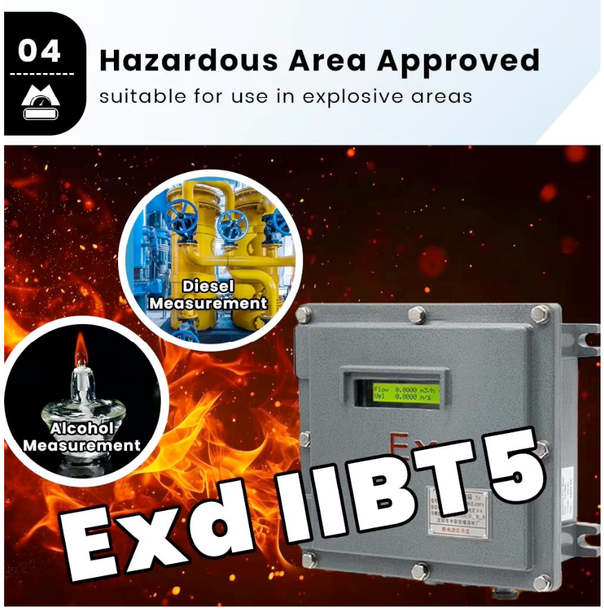
Flow meter for Diesel, LPG & Gases
Flow meter for compressed air
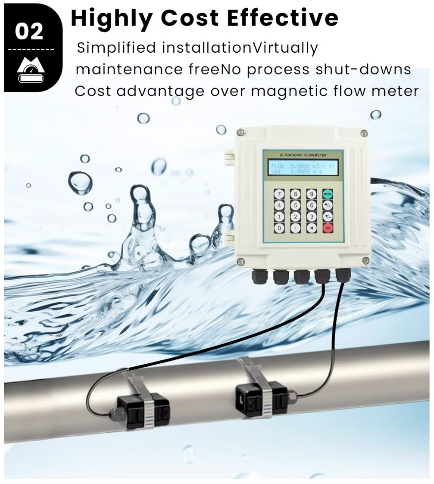
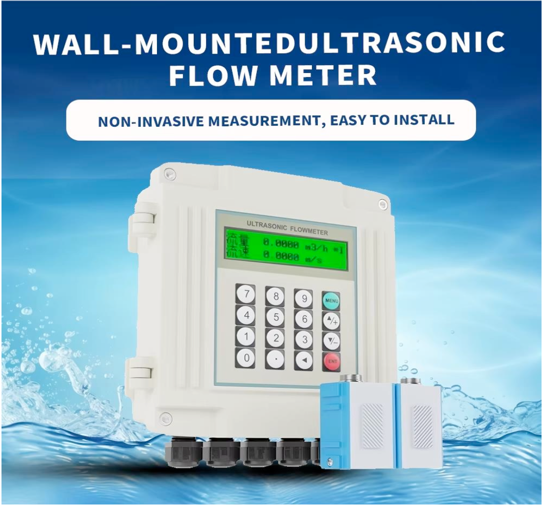
Non contract flow meter
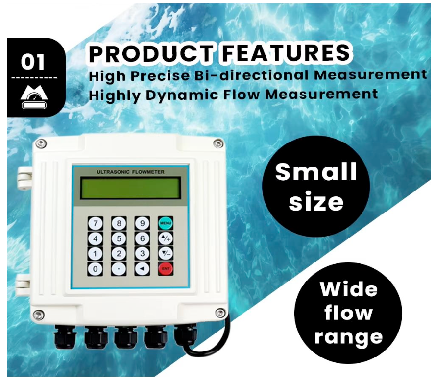
Non Contract Flow Meter
| Product Name | Ultrasonic Flowmeter |
| Accuracy | ±1% of reading at rates > 0.2 m/s |
| Repeatability | 0.2% |
| Measuring Principle | Transmit time |
| Velocity Range | Up to ±32 m/s |
| Pipe Size | DN15mm – DN6000mm |
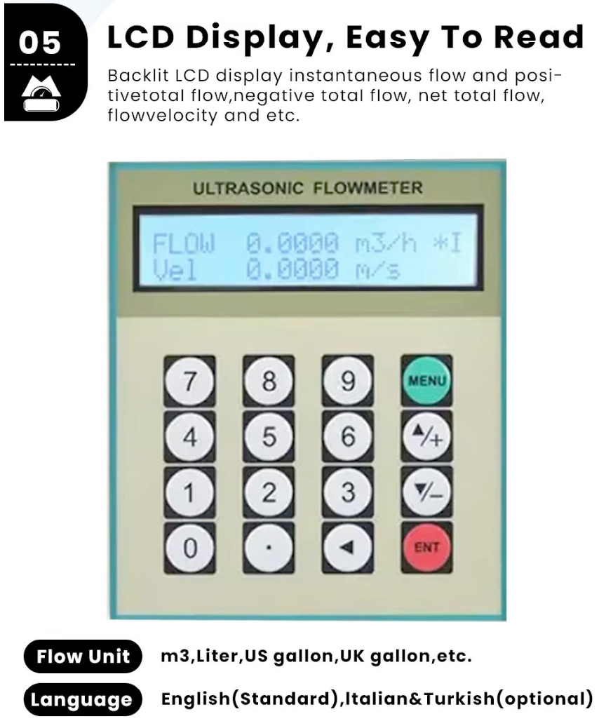
| Display | LCD with backlight, shows accumulated flow/heat, instantaneous flow/heat, velocity, time, etc. |
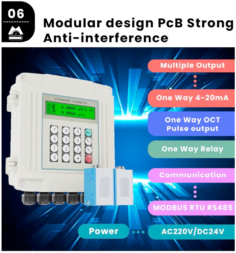
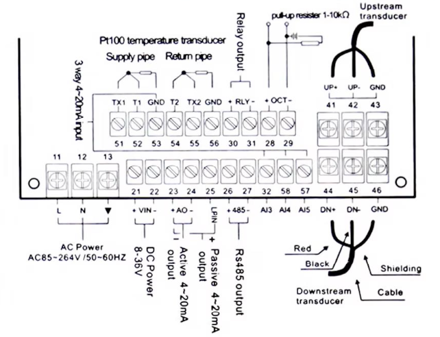
| Signal Output | 1 way 4-20mA output; 1 way OCT pulse output; 1 way relay output |
| Signal Input | 3 way 4-20mA input for heat measurement via PT100 platinum resistor |
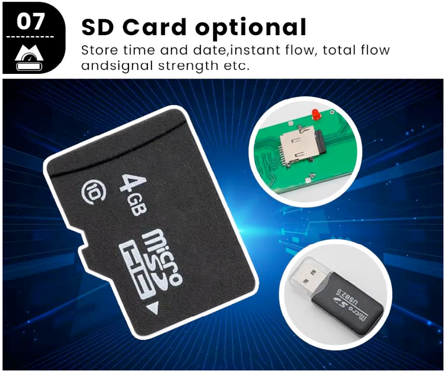
| Other Functions | Records forward, reverse, and net accumulated flow & heat; logs power on/off time and last 30 flow rates; supports Modbus communication |
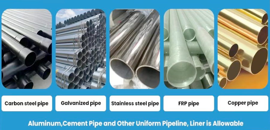
| Pipe Material | Carbon steel, stainless steel, cast iron, cement, copper, PVC, aluminum, FRP, etc. (liner allowed) |
| Straight Pipe Section | Upstream: 10D; Downstream: 5D; From pump: 30D (D = pipe outer diameter) |
| Liquid Types | Water, seawater, industrial sewage, acid & alkali liquid, alcohol, beer, oil, and other homogeneous liquids |
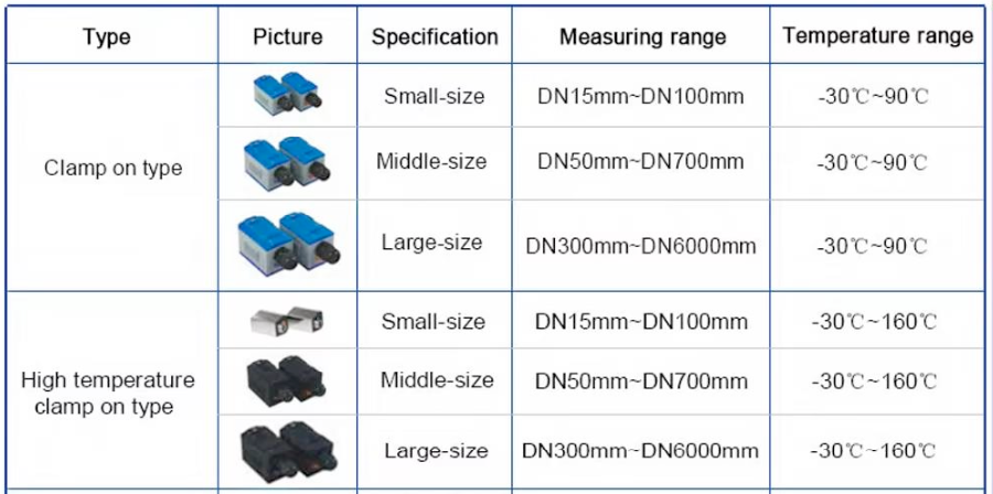
| Liquid Temperature | Standard: -30°C ~ 90°C; High-temperature: -30°C ~ 160°C |
| Liquid Turbidity | Less than 10000 ppm, with a small number of bubbles |
| Flow Direction | Bi-directional flow and heat measurement |
| Environment Temperature | Main Unit: -30°C ~ 80°C; Transducer: -40°C ~ 110°C |
| Environment Humidity | Main Unit: ≤85% RH; Transducer: IP65 (standard), IP68 (optional) |
| Cable | Twisted pair line, 5m standard (extendable to 500m, contact manufacturer for longer); RS-485 interface up to 1000m |
| Power Supply | AC 220V or DC 24V |
| Power Consumption | Less than 1.5W |
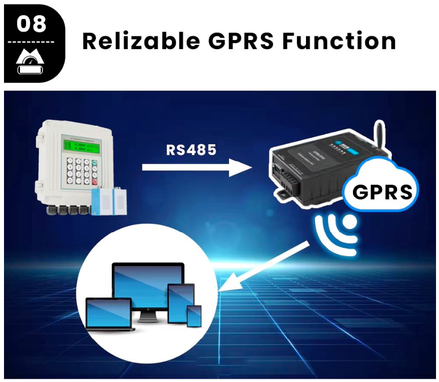
| Communication | MODBUS RTU via RS-485 |
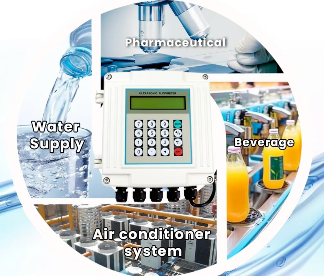
Applications
Widely used for water supply, non conductive liquid such as the distilled wa- terfood oil &light oil, boiler fuel oil engine for diesel measurement, and air- conditioner system to measure the flow & heat, food and beverage, phar- maceutical, ballast water, fuel consumption and other processeson-board ships, etc.
Ultrasonic Flowmeter Selection
Installation Selection
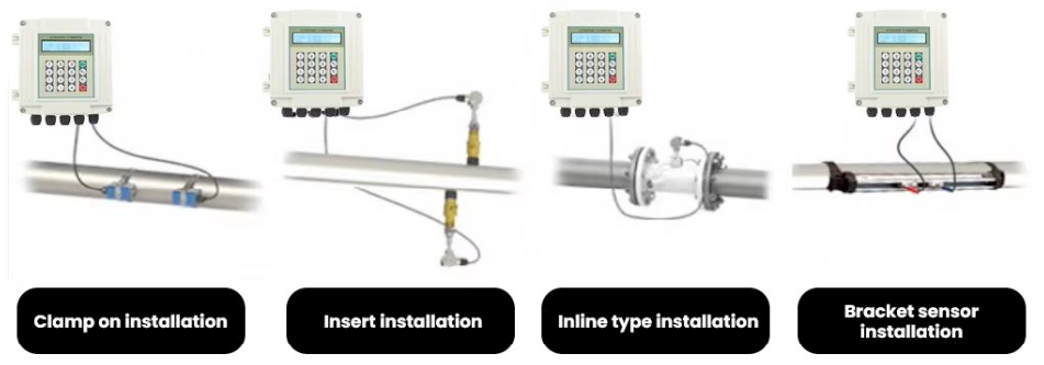
- Bracket clamp sensor with clear scale, accurateinstallation assured and more convenient
- If pipe material is fiberglass or cement, needselect insertion transduce
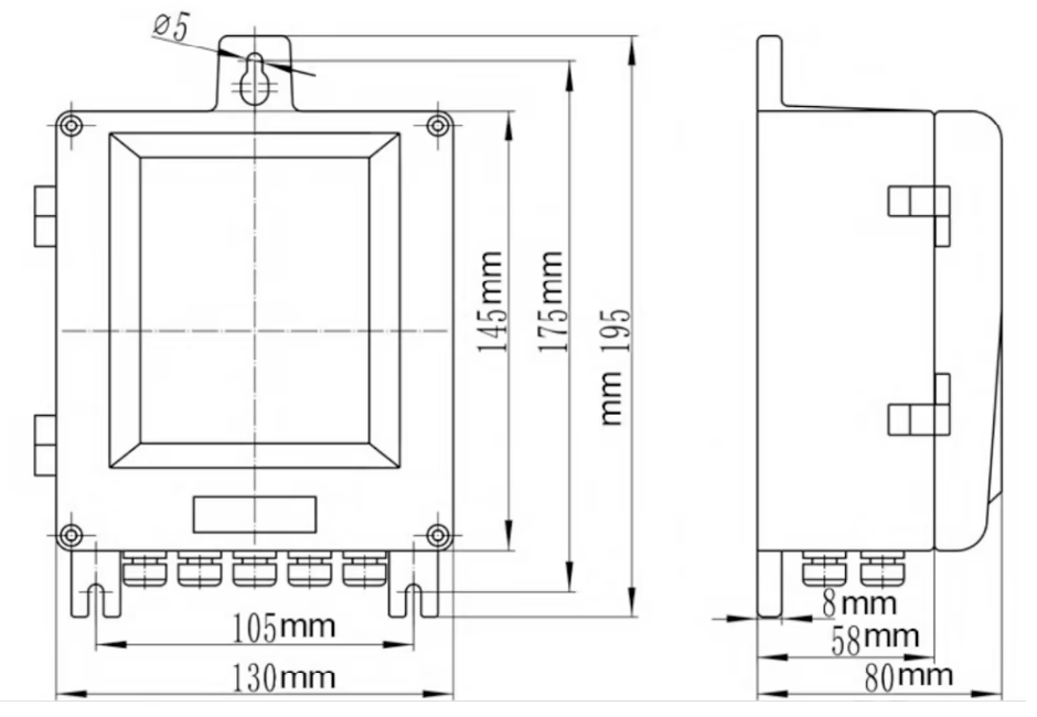
Size Chart
Compatible with Many Material Pipes
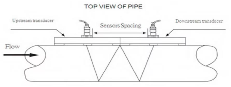
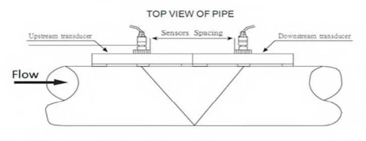
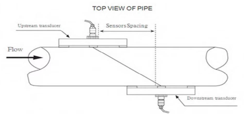
Transducers Installation
V-method Installation
V-method installation is the most widely used mode for daily measurementwith pipe inner diameters ranging from 15 mm to 200 mmit is also called reflective mode.
Z-method Installation
Z-method is commonly used when the pipe diameter is between 300mmand 500mm
W-method Installation
W-method is usually used on plastic pipes with a diameter from 15mmto 100mm