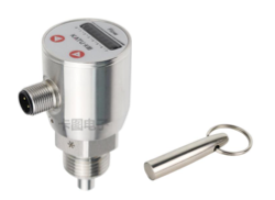
Electronic flow switch FS210
Principles characteristics
FS210 series heat flow switch adopts heat diffusion principle. There are two temperature sensors in the probe: one is used as a reference sensor to measure the temperature of the medium, and the other is used as a measure- ment sensor after being heated. The tempera- ture difference between the two sensors is used as the basis for measuring the flow velocity. When the flow velocity of the medium increases, the temperature difference decreases, and vice versa. The temperature difference value is converted into standard electrical signal and displayed after processing.
The FS210 series are all designed with all-metal shell, with 8-bit LED showing flow trend and switching status. One product is suitable for various pipe diameters. It can be set by keyboard or computer. No moving parts, mainte- nance-free, can be used in a variety of media.
- wide range
- through the button switch point or defined range More parameters can also be set by handheld Settings or computer
- 8 LEDS show flow trend and on/off status
- PNP/NPN/ relay electrical output optional
- Easy to operate inductive button setting
- Protection level IP67
- Small structure diameter 36mm
- The outgoing direction can be rotated by 330°
Product application
- Hydraulic/lubrication
- Pump
- Cooling system
- Ventilation system
- water treatment
- Leak detection
Technical parameters
- Measuring range
Water: 1... 150cm/s (the default display value is demarcated in water and specified in other media)
Oil: 3... 300cm/s
Air: 20... 2000cm/s - Measuring medium: water, oil, gas, and other compatible stainless steel medium
- Repetitive accuracy: 1% @ <0.6m/s; 3% @ <1.5m/s; 10% @ >1.5m/s
- Pressure: 100bar (300bar optional)
- Initialization time: 1... 8s
- Response time: Typical value 2s
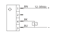
- Power supply voltage: 12... 30Vdc
- No-load current consumption: ≤40mA, at 24Vdc power supply
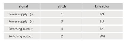
- Switch output (normally open + normally closed)
Output type: PNP/NPN/Relay optional, normally on/normally off can be set
Load capacity: 500mA at 24Vdc power supply (NPN and PNP type), 60W (relay type) - Wiring protection: Reverse phase, overload, short circuit protection
- Display
Design: 3 red LEDs (flow rate < switching point)
1 yellow LED (flow rate = switching point)
4 green LEDs (flow velocity > switching point) - Temperature
Working/storage temperature: -40... 85℃
Medium temperature: -20... 85℃ - Material
Case: stainless steel 304
Probe: stainless steel 304 / stainless steel 306L - Protection grade: IP67
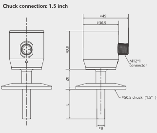
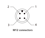
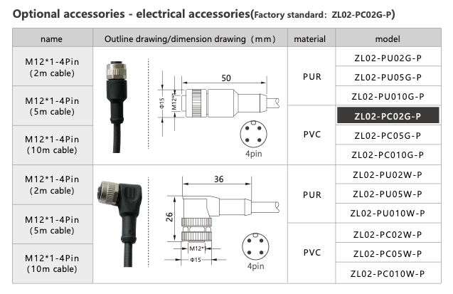
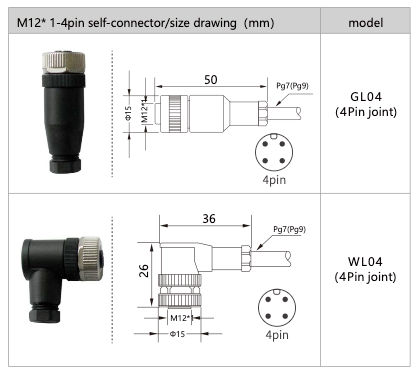
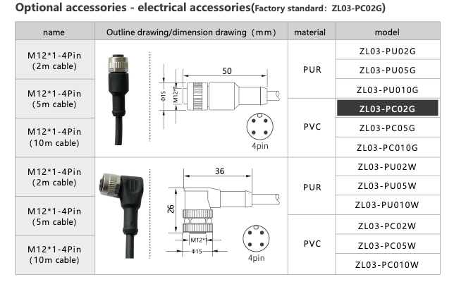
- Appearance: M12×1 connector
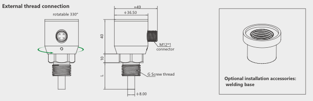
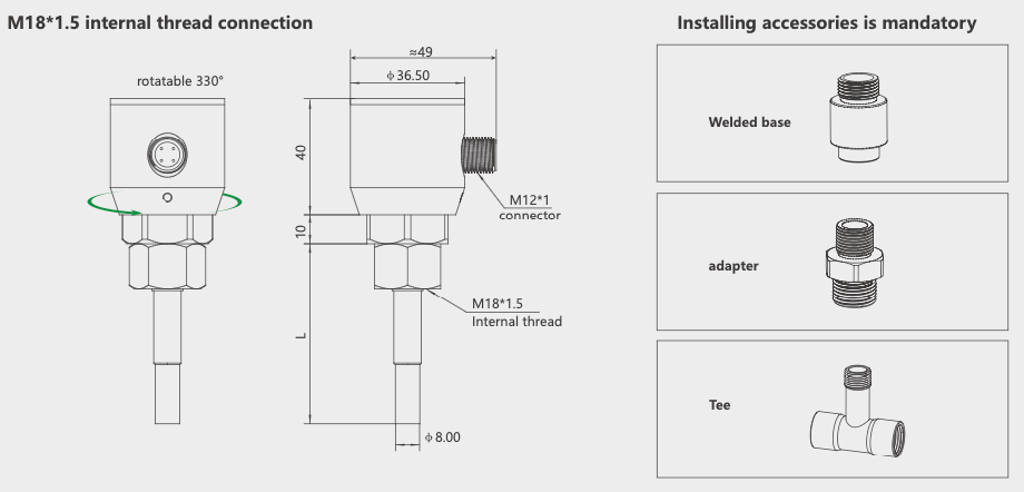
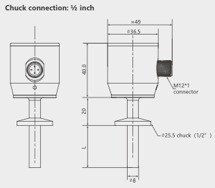
Dimensions (mm)
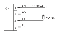
Wiring diagram
PNR
NPN
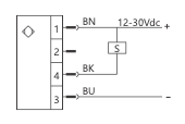
Relay Output
Selection Table
| FS210- | P | G12M | L30 | expatiate |
|---|---|---|---|---|
| FS210- | Hot flow switch | |||
| P | PNP output (3-core cable) | |||
| N | NPN output (3-core cable) | |||
| C | Relay output (4-core cable) | |||
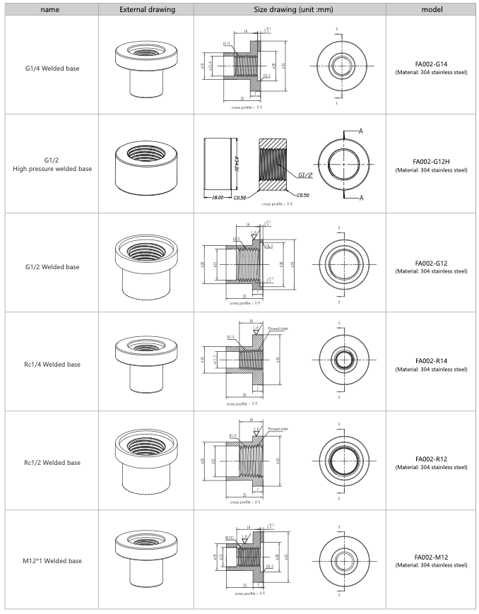
| G12M | Process connection: G1/2 external thread | |||
| G14M | Process connection: G1/4 external thread | |||
| R12M | Process connection: R1/2 external thread | |||
| R14M | Process connection: R1/4 external thread | |||
| M18K | Interface thread M18 × 1.5 internal thread (used with mounting accessories, easy to rotate and adjust in the field installation direction) | |||
| H25 | Outer diameter 25.5mm, chuck connection (GB: ISO2852-1993) | |||
| H50 | Outer diameter 50.5mm, chuck connection (GB: ISO2852-1993) | |||
| L25 | Rod length L=25mm (≤DN10) (Only external thread is optional) | |||
| L30 | Rod length L=30mm (≥DN15) (Only external thread is optional) | |||
| L50 | Rod length L=50mm (≥DN40) (Only external thread is optional) | |||
| L60 | Rod length L=60mm (M18 internal thread applicable diameter: ≥DN15; Diameter for external thread: ≥DN50) | |||
| L80 | Rod length L=80mm (M18 internal thread applicable diameter: ≥DN40; Diameter for external thread: ≥DN80) |
Welded base (M18 internal thread only optional)
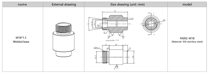
Welded base (optional external thread only)
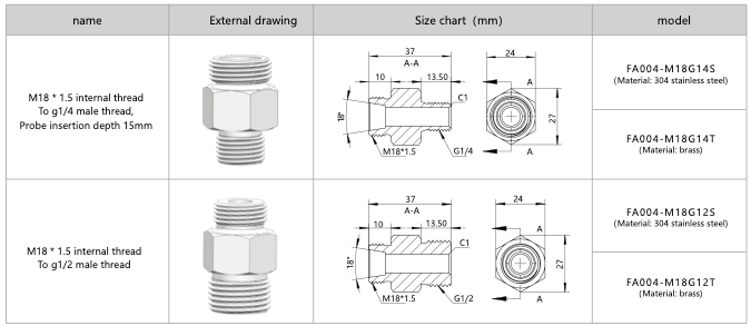
Adapter (M18 internal thread only optional)
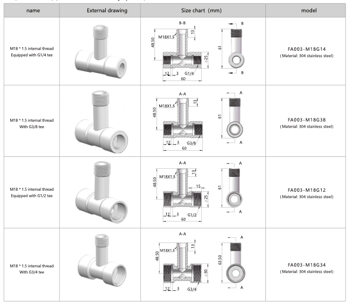
Tee (stainless steel) (M18 internal thread only optional)
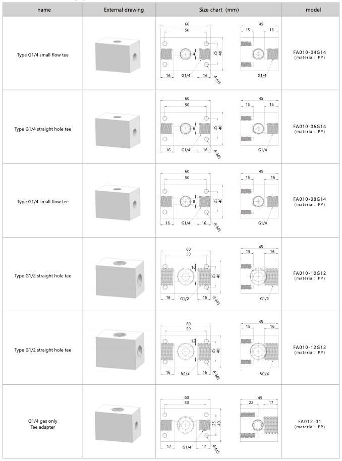
Tee (PP) (external thread only optional)
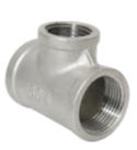
Tee (Conventional stainless steel: 40bar) (external thread only optional)
| Conventional tee | |||
|---|---|---|---|
| Diameter of thread | Inch code | Pipe thread (R) | Model number |
| DN15 | 4 points | 1/2 | FA013-R12K |
| Reducing tee | |||||
|---|---|---|---|---|---|
| Diameter of thread | Inch code | Pipe thread left (R) | Pipe thread center (R) | Pipe thread right (R) | Model number |
| DN20 | 6 points x points | 3/4 " | 1/2" | 3/4 " | FA013-R12KR34K |
| DN25 | 1 inch x 4 points | 1" | 1/2" | 1" | FA013-R12KR1K |
| DN32 | 1.2 inches x 4 points | 1.2 " | 1/2" | 1.2 " | FA013-R12KR1.2K |
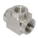
Tee (high pressure stainless steel: 200bar) (external thread only optional)
| Conventional tee | |||
|---|---|---|---|
| Diameter of thread | Inch code | Pipe thread (R) | Model number |
| DN15 | 4 points | 1/2 | FA014-G12K |
| Reducing tee | |||||
|---|---|---|---|---|---|
| Diameter of thread | Inch code | Pipe thread left (R) | Pipe thread center (R) | Pipe thread right (R) | Model number |
| DN20 | 6 points x 4 points | G 3/4 " | G 1/2" | G 3/4 " | FA014-G12KG34K |
| DN25 | 1 inch x 4 points | G1" | G1/2" | G1" | FA014-G12KG1K |