Safety LIDAR sensor for navigation and safety
LIDAR Sensors MWLE-M10 series
Product features/panel description
- Lidar detection range up to 20 meters.
- The effective scanning angle is 300° and the scanning frequency is 25 revolutions per second.
- Up to 16 alarm zones can be set via the software, each containing 3 user-definable alarm zones.
- Lidar integrated object scanning detection and data transmission functions, can be mounted on a mobile vehicle or a fixed position, compact design, small footprint, easy to install, maintain and dismantle.
- It is resistant to rain splash and short-term water immersion, and has strong anti-interference to ambient light such as daylight.
- Ring scanning optical window;
- Three warning zone alarm lights;
- Digital tube display;
- USB data interface;
- Aerial plug cable socket.
Input/output circuit diagram
| Serial number | Color | Signal definition | Signal description |
|---|---|---|---|
| 1 | / | Dedicated RJ45 network cable plug | |
| 2 | Red | Positive electrode | Radar power positive, +9~28V |
| 3 | Black | negative electrode | Radar power supply negative, 0V |
| 4 | Red | VDD | User alarm signal power positive +5~80V, maximum 50mA |
| 5 | Black | GND | User alarm signal power supply negative 0V 100 |
| 6 | Yellow | IN1 | Alarm area selection control input |
| 7 | Green | IN2 | |
| 8 | Blue | IN3 | |
| 9 | White | IN4 | |
| 10 | Orange | Instruct | Set low when there is an error in the radar |
| 11 | Brown | OUT3 | Alarm level output (high level = there is an obstacle in the alarm area) |
| 12 | Grey | OUT2 |
Product parameter/model/size chart
| Model number | LE-M0 |
|---|---|
| Maximum range | 20/40m |
| Accurate | ±2cm |
| Scanning angle | 300° |
| Scanning frequency | 25 turns/second |
| Angular resolution | 0.1 / 0.25 selectable |
| Response time | 40 milliseconds |
| Output method | USB/ethernet |
| Output point frequency | 20 kbps |
| Supply voltage | DC 9-30 volts |
| Power wastage | <3W (typical 2.4W) |
| Environmental conditions | Operating: -10°C~55°C (no frost and condensation) 35%-85%RH |
| Storage: -40°C~70°C, 35%~95% RH | |
| Area group switching | 4 sets of external input signals (Z1\Z2\Z3\Z4) to realize 16 zones switching |
| Waterproof and dustproof grade | IP65 |
| Laser type | Infrared 905nm wavelength, safe Class I laser, no special protection required |
| Resistant to ambient light interference | 30000Lux |
| Electromagnetic compatibility (EMC) | EMI |
| EMS | |
| EN61326 1:2013 EN61326 1:2013 EN61000-4-4:2012 |
|
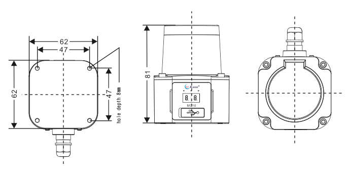
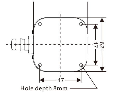
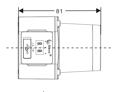
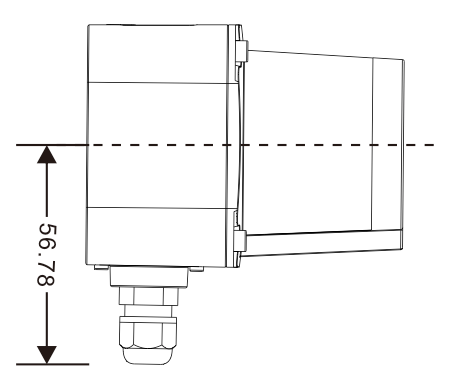
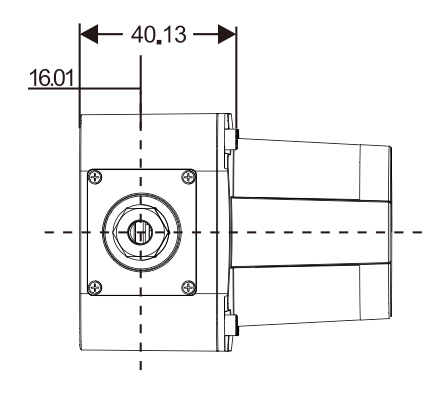
| Overall dimensions | 62mm*62mm*80mm |
Digital tube display meaning/working mode
| Digital display | Content meaning and description |
|---|---|
| 00 | Display after startup |
| 0.0 to 9.9 | After connecting to the network, the last two digits of the IP address will be displayed, with one decimal illuminated representing one hundred digit and two decimals illuminated representing two hundred digits. For example, if the IP address is 192.168.1.168, the digital tube will display "6.8." and keep flashing to indicate the last digit of the IP address is .168. |
| 01 | The current alarm area is area group 1 |
| 02 | The current alarm area is area group 2 |
| 03 | The current alarm area is area group 3 |
| 04 | The current alarm area is area group 4 |
| 05 | The current alarm area is area group 5 |
| 06 | The current alarm area is area group 6 |
| 07 | The current alarm area is area group 7 |
| 08 | The current alarm area is area group 8 |
| 09 | The current alarm area is area group 9 |
| 10 | The current alarm area is area group 10 |
| 11 | The current alarm area is area group 11 |
| 12 | The current alarm area is area group 12 |
| 13 | The current alarm area is area group 13 |
| 14 | The current alarm area is area group 14 |
| 15 | The current alarm area is area group 15 |
| 16 | The current alarm area is area group 16 |
| FF | Indicates that the machine is malfunctioning and not working properly. |
| 22 | Indicates successful machine configuration and saves data (blinks twice) |
Digital tube display meaning table
Operating mode
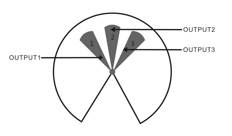
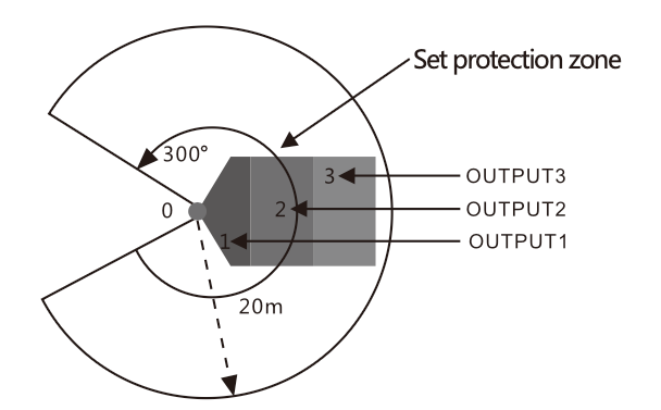
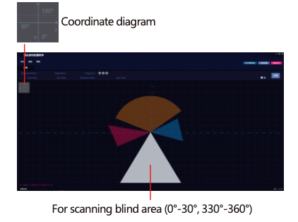
Table of preset maps and warning signals for 3 warning zones in a 300°x20 m sector detection area
| Serial number | Hidden meaning | Descriptive |
|---|---|---|
| 0 | Obstacle avoidance /navigation lidar | Scanning range 300°, scanning radius 20 meters (70% reflectivity) or radius 8 meters (10% reflectivity). Note: Not applicable to transparent or small objects such as wire rods with weak reflectivity. |
| 1 | User-configured alarm zone 1 | When detecting an obstacle in an alarm area corresponding to the OUTPUT1/2/3 alarm line to do high and low level conversion, the available configuration software to choose whether the low-to-high NPN or high-to-low PNP, the factory preset is low-to-high NPN, that is, there is an obstacle = the alarm line is powered, no obstacle = no power to the alarm line |
| 2 | User-configured alarm zone 2 | |
| 3 | User-configured alarm zone 3 |
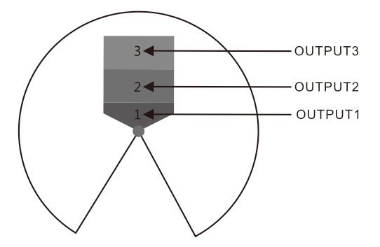
Operating mode ①
Users can configure any 1~3 alarm zones from far and near, corresponding to the output signal for OUTPUT1, OUTPUT2, OUTPUT3; (the illustration only draws three small sectors, in the software settings can be drawn to cover any angle of any fan area)
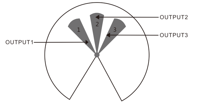
Operating mode ②
Users can configure mutually independent 1 ~ 3 fan-shaped warning area, corresponding to the output signal OUTPUT1, OUTPUT2OUTPUT3; (the illustration only draws three small sectors, in the software setup can be drawn to any fan to cover any angle)
MWLE-10 Type 2D Lidar User Guide
Chapter 1 Lidar Product Description
Thank you for purchasing and using the LE-10 2D Lidar products provided by Shenzhen Leraun T echnology Co., Ltd. Please read this user guide carefully before use.
Safety instructions
Note: In order to use the LE-10 series lidar safely, please be sure to follow all the information with warning signs in this user guide to avoid possible injury :
- Please install and use this instrument by professional technicians.
- Please connect the lidar with other devices only when the power is turned off.
- Install within the environment (temperature, humidity, shock, and vibration, etc.) specified in this manual during installation.
- Do not install in a place with flammable or explosive gas.
- Do not install in places with dense smoke, particles, corrosive chemicals, or other harmful substances.
- When the USB interface is not in use, press the USB sealing cover tightly to prevent dust from entering and affecting performance.
- Do not disassemble the instrument at will; any damage caused by disassembly will not be covered under warranty.
Product overview
Leraun LE-10 series lidar is an intelligent sensor used to detect and monitor objects in the surrounding area of the radar and output real-time position data of objects. The LE-10 series radar calculates the distance and azimuth of the detected object through the round-trip time and angle of the emitted laser, and completes the perception and two-dimensional positioning of one or more surrounding objects. LE-10 series lidar detection range is up to 20 meters, the effective scanning angle is 300, the scanning frequency is 25 revolutions per second, the output rate of detection data is 20 thousand per second, and up to 16 groups of alarm areas can be set through the supporting software , each group of alarm areas contains 3 user-definable alarm areas. LE-10 series lidar emits 905nm low-power infrared pulsed laser, which belongs to a class of safety laser, which is safe for human eyes and has high stability and reliability. The waterproof and dustproof grade of the radar reaches IP65, which can prevent rainwater splashing and short-term immersion in water, and has strong anti-interference ability to ambient light such as fluorescent lights. LE-10 series lidar integrates object scanning detection and data transmission functions, and can be installed on mobile vehicles or fixed positions.
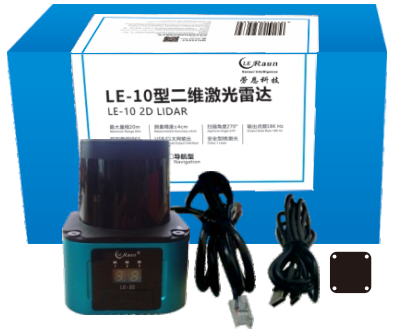
Product Configurations and Accessories
The standard configuration of the LE-10 series lidar includes a lidar, an aviation cable, a USB cable, a rubber shock pad and Windows version adapter software. The user's computer can connect the laser radar through the USB cable or the network cable in the aviation cable. Through the adaptation software, the relevant parameters such as the alarm area group can be set and the scanning results of the radar can be observed. For the specific setting methods and steps of the LE-10 series radar, please refer to Chapter 2 "Lidar Configuration Software Instructions" in this user guide.
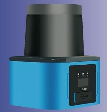
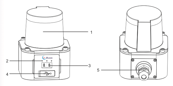
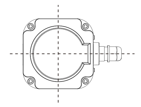
Product appearance and logo
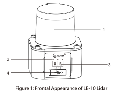
- Ring scanning optical window.
- Three warning lights in the warning area.
- Digital tube display screen.
- USB data interface.
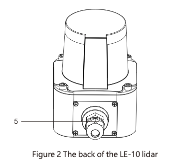
Aviation cable socket.
| Digital screen display | Content meaning and description |
|---|---|
| 00 | Displayed after booting |
| 0.0 to 9.9 | After connecting to the network, the last two digits of the IP address will be displayed. One decimal is lit to represent the hundreds digit 1, and two decimals are lit to represent the hundreds digit 2, 0.0 to 9.9. For example, the IP address is 192.168.1.168, the digital tube displays "6.8." and blinks all the time, indicating that the IP address ends with "168". |
| 01 | The current alarm area is area group 1 |
| 02 | The current alarm area is area group 2 |
| 03 | The current alarm area is area group 3 |
| 04 | The current alarm area is area group 4 |
| 05 | The current alarm area is area group 5 |
| 06 | The current alarm area is area group 6 |
| 07 | The current alarm area is area group 7 |
| 12 | The current alarm area is area group 12 |
| 13 | The current alarm area is area group 13 |
| 14 | The current alarm area is area group 14 |
| 15 | The current alarm area is area group 15 |
| 16 | The current alarm area is area group 16 |
| FF | Indicates that the machine is faulty and cannot work properly. |
| 22 | Indicates that the machine is successfully configured and the data is saved. (Blinks twice) |
LE-10 lidar dimensions (Unit mm)
Warn
- Be sure to connect with power off.
- Double insulation or reinforced insulation must be used between all input and output interfaces and dangerous voltages; otherwise, it may cause electric shock.
- The data cable of the lidar should be kept away from high-voltage wires, power lines, transformers, and other sources of electromagnetic interference.
- Do not replace cables without permission.
- Please connect the wire properly.
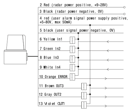
Typical Wiring Diagram
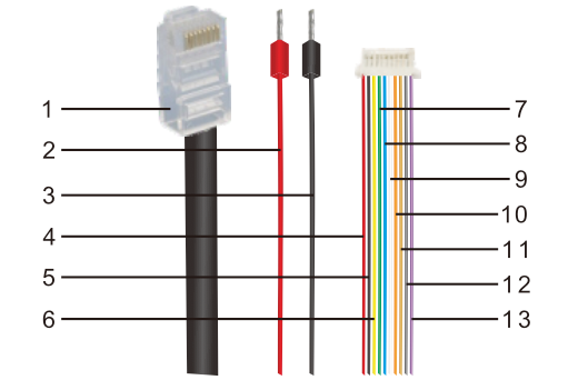
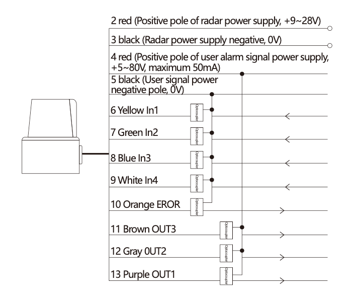
| Serial number | Color | Signal definition | Signal description |
|---|---|---|---|
| 1 | / | Dedicated RJ45 network cable plug | |
| 2 | Red | Positive electrode | Radar power positive, +9~28V |
| 3 | Black | negative electrode | Radar power supply negative, 0V |
| 4 | Red | VDD | User alarm signal power positive +5~80V, maximum 50mA |
| 5 | Black | GND | User alarm signal power supply negative 0V 100 |
| 6 | Yellow | IN1 | Alarm area selection control input |
| 7 | Green | IN2 | |
| 8 | Blue | IN3 | |
| 9 | White | IN4 | |
| 10 | Orange | Instruct | Set low when there is an error in the radar |
| 11 | Brown | OUT3 | Alarm level output (high level = there is an obstacle in the alarm area) |
| 12 | Grey | OUT2 | |
| 13 | Purple | OUT1 |
Installation and enabling steps of LE-10 lidar
- Use 4 M4 screws (provided by the user according to the thickness of the mounting plate) through a piece of rubber shock pad in the accessories to firmly fix the radar bottom case on the vehicle, action arm or fixed position.
- Insert the three plugs at the end of the aviation cable: the power plug, the special network cable plug, the selection of the alarm area and the alarm plug firmly.
- After the screw connection and electrical connection are confirmed to be correct, the radar can be powered on and preheated for two or three minutes. After the radar is powered on, it will automatically start a circular scan of the surrounding area. (Note that objects such as controlled vehicles and action arms must be immovable before powering on for the first time to avoid accidents)
- Use a personal computer to connect the radar through a network cable or USB cable, start the radar adaptation software, first connect the device in the menu, and then click the "Start" button on the interface, let the computer start to receive the scanning detection data of the radar data port, and check the computer screen. Whether the displayed measured object (shown as a dot on the screen) matches the real object.
- Use the computer to check whether one or several groups of alarm area settings preset in the radar by the manufacturer meet your needs. If not, you can modify the preset alarm area map or create a new drawing. After the drawing is completed, it is recommended that the user set the self-drawing area. Save to new group, do not overwrite factory preset map. After saving the image, select it and then apply it.
- Deliberately put objects into the three warning areas successively, check whether the three warning lights on the front panel of the radar light up successively, and detect whether the corresponding three warning signal lines in the aviation cable are high-level and no objects when there are objects. is low level.
- After the warning signal of the lidar is verified to be normal,the trial can be started. Note that the first movement of the vehicle, action arm, etc. needs to be started in a safe and open environment with manual emergency stop means at all times. Do not run the vehicle and action arm after power-on! Use a personal computer to check the radar scan image for any abnormality before power-on, and confirm that the strong working current and electromagnetic radiation of the vehicle and action arm will not interfere with the radar's work. Then artificially put in the object, let the vehicle and the action arm start to move in the controllable environment, if the movement logic in several common obstacle environments is in line with the intention of use, you can start the field
●For software operation, please refer to Chapter 2 "Lidar Configuration Software Instructions" .
LE-10 type lidar technical parameter table
| Parameter | Value |
|---|---|
| Maximum range | 20m (70% reflectance white object); or 8m (10% reflectivity black object) |
| Precision | ±2cm |
| Scan angle | 300° |
| Scanning frequency | 10–25Hz |
| Angular resolution | 0.1° / 0.25° |
| Response time | 40ms |
| Output method | USB / Ethernet |
| Output frequency | 30K/S |
| Voltage | DC 9–28V |
| Power consumption | <3W (2.4W typical) |
| Environmental conditions |
Working: -10°C ~ 55°C (no frost, condensation), 35% ~ 85% relative humidity Storage: -40°C ~ 70°C, 35% ~ 95% relative humidity |
| Zone group switch | 4 groups of external input signals (IN1, IN2, IN3, IN4) realize the switching of 16 areas |
| Waterproof and dustproof grade | IP65 |
| Laser type | Infrared wavelength of 905 nanometers, safety type I laser without special protection |
| Anti-ambient light interference | 3000 lux |
| Dimensions | 62 × 62 × 81 mm |
| Electromagnetic Compatibility (EMC) | EN61326-1:2013 |
Working mode
| PS510- | 001 | G14K | G14K | S2 | expatiate |
|---|---|---|---|---|---|
| 0 | Obstacle avoidance/navigation lidar | The scanning range is $300^{\circ}$, and the scanning radius is **20 meters** (70% reflectivity) or **8 meters** (10% reflectivity). Note: It is **not suitable for small objects** such as transparent or thread rods with weak reflection. | |||
| 1 | User-configured alarm zone 1 | When an obstacle is detected in an alarm area, the corresponding **OUTPUT1/2/3 alarm lines** are converted into high and low levels. | |||
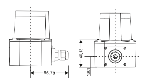
| 2 | User-configured alarm zone 2 | The configuration software can be used to select whether it is low to high **NPN** or high to low **PNP**. The factory default is low to high NPN. That is, there is an obstacle = the alarm line has power and there is no obstacle = the alarm line has no power | |||
| 3 | User-configured alarm zone 3 | ||||
The LE-10 lidar provides 2 working modes, the user can modify the working mode through the configuration software, and can set up to 16 groups of alarm zones, and choose one of them.
Working mode ①
The user can configure any 1 to 3 alarm zones from far to near, and the corresponding output signals are OUTPUT1, OUTPUT2, OUTPUT3; The illustration only draws three small sectors, in the software settings, any sector can be drawn to cover any angle
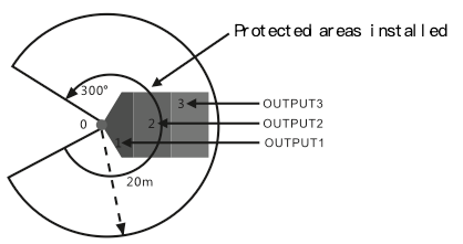
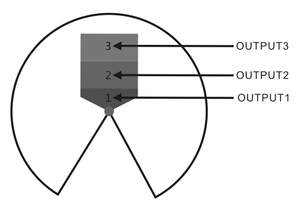
Working mode ②
The user can configure 1~3 sector-shaped alarm areas which are independent of each other, corresponding to the output signals OUTPUT1, OUTPUT2, OUTPUT3; (the figure only draws three small sectors, in the software setting, any sector can be drawn to cover any angle)
Chapter 2 Lidar Configuration and Instructions for Use
Software operating environment requirements
The personal computer on which this software is installed must be installed with .net Framework 4.0 and above, and support Windows systems above XP/win7
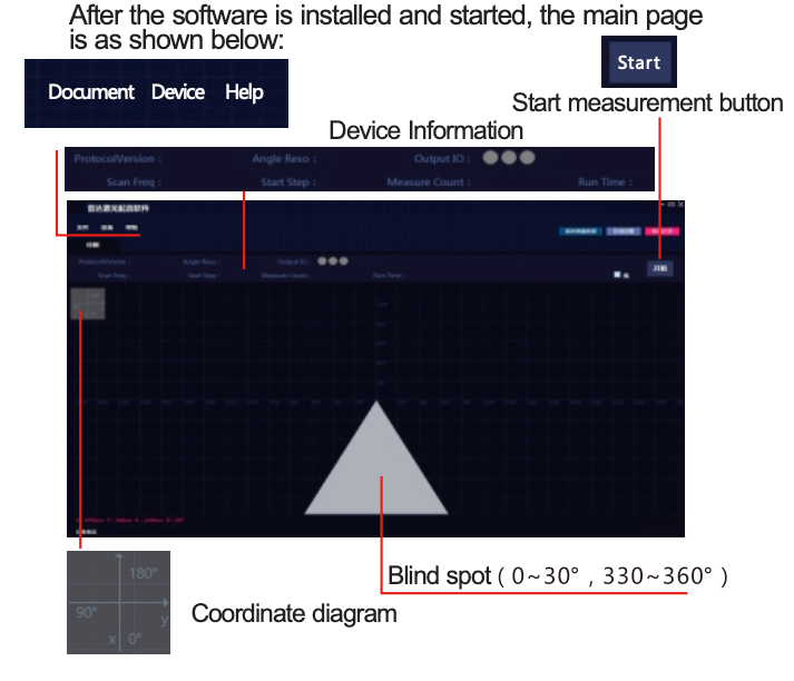
Introduction to the main interface of the software
After the software is installed and started, the main page is as shown below:
Introduction to software function operation
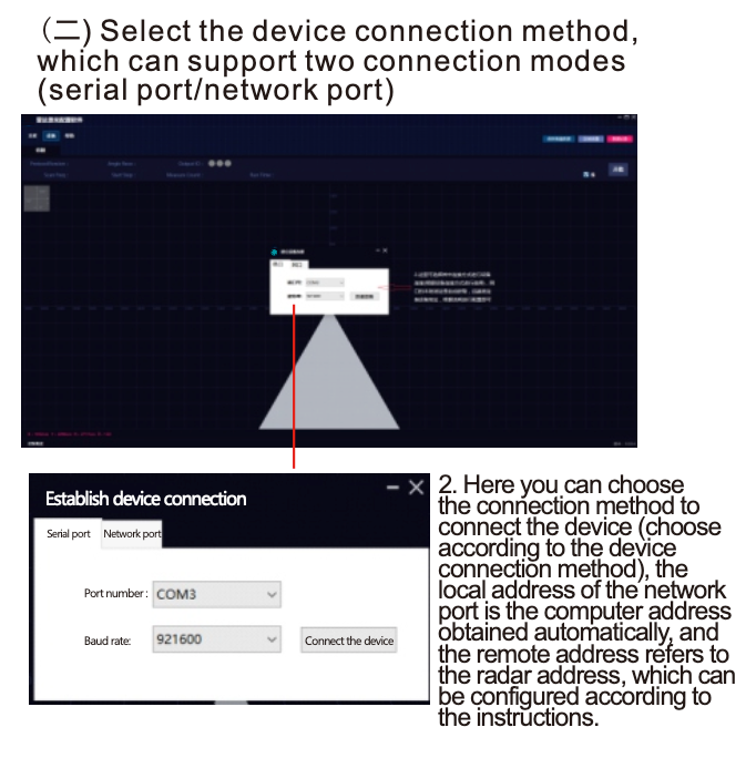
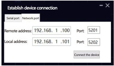
(三) Select the connection method Serial port: Connect the wires according to the serial port wiring diagram below. Select the port number, which is COM3 in the example picture (different computers will assign different COM numbers to the CP210x serial port of the radar. If the correct COM number is not displayed in the drop-down box, you need to install the CP210x driver that comes with the radar software, or check whether The radar is not turned on, the USB cable is not connected and cannot be detected), the baud rate remains unchanged at 921600, and click to connect the device. Note that other baud rates are not available.
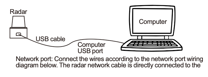
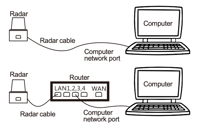
computer network port, and a router or switch can be connected in the middle to extend the relay. UDP transmission protocol, the local address of the computer is automatically obtained; the remote address (referring to the radar address) is configured according to the IP displayed on the radar panel.
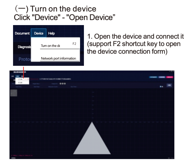
Device connection
When the device is successfully connected, you will see "device online" at the bottom left of the interface, and the start button is in the active (available) state;
If the device is online and the start button is not activated, the device is in a false connection state, please check the device connection parameters and whether the connection line is loose.
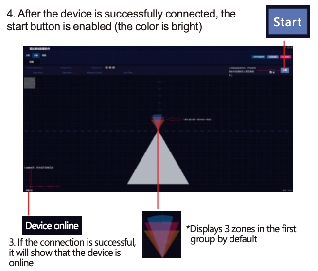
If the alarm area data is pre-stored in the device, it will be displayed (the first group is displayed by default).
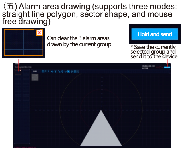
Alarm area drawing (supports three modes: straight line polygon, sector shape, and mouse free drawing)
1. Regional settings
A maximum of 16 groups of protection areas can be set under the area settings, and each group of areas can be set with 3 alarm area data, and each alarm area is represented by a different color.
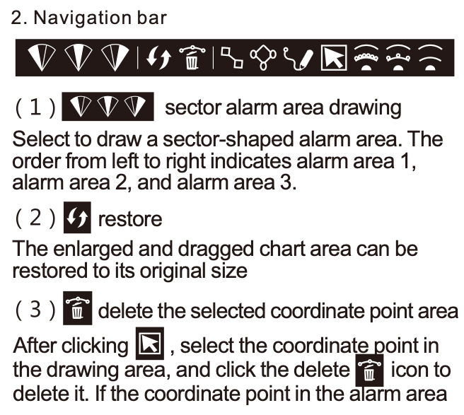
2. Navigation bar
(6) Save and send function
After drawing the alarm area, click save and send to write the data of the alarm area of the currently selected area group into the device. Tip: Save and send operations can only be performed after the device is successfully connected! The newly saved alarm zone will take effect only after the radar is powered off and restarted.
Introduction of measurement operation
1. Click the "Start" button on the right to start the measurement
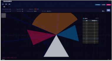
2. Click "Pause" to stop the device : The two states displayed by the device work are as follows: point and line. Save measurement data, you can save the graph (data) measured in the current state to the MeasureData folder in the software installation directory, the file name is named after the current time point
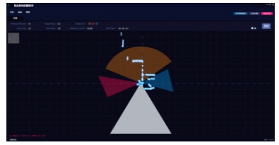
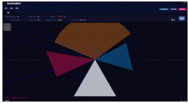
3. In the data recording area, the measurement data of 30-330° will be displayed. Only when it is in the measurement state, the real-time data display will appear in the list.
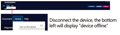
Disconnect the device and exit
Click "Device" in the upper left menu, click " Disconnect Device”
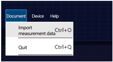
Click "File" in the upper left corner menu, click "Import measurement data" to import the txt data text saved during measurement
Click on the upper left menu "File" , click "Exit" the current system
Network port settings
Click "Device" - "Network Port Information" to enter the static IP configuration, set the IP address, subnet mask, gateway and port, and click OK to save the IP information to the device.Note: Before setting the network port, you must first connect the device, and perform IP configuration in the state of stopping the measurement.
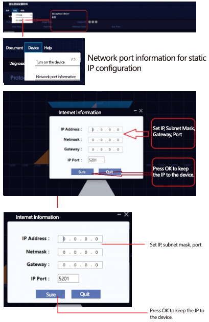
When the IP Address is set to 0.0.0, it is the dynamic acquisition mode, and the other is the static IP mode, such as 192.168.1.1mn (the nixie tube always displays m.n after the radar is turned on. For example, if it displays 0.0, set the radar IP Address to 192.168.1.100) . It is recommended to set the IP and Port of the computer to be similar to the radar but not the same. For example, only the last digits are different, so the two are easy to connect. The figure below is a sample setting when the radar digital tube displays its own address as 0.0.
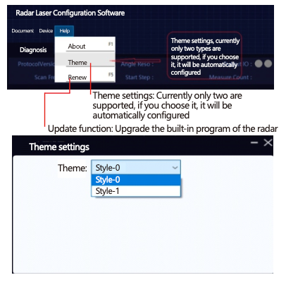
Theme setting
Click "Help" - "Theme" to set. Currently, only two themes are supported: 0-dark background and 1-light background. After selection, it will be automatically configured.
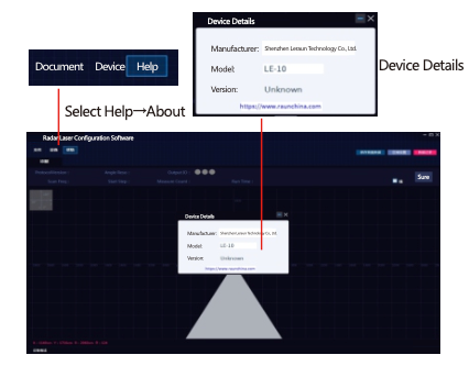
About the equipment
Click "Help" - "About" - "Device Details" to view the version information of radar and built-in programs.