Gas detectors
Flame Detector
Safety door switches
Safety light curtains
Safety LIDAR sensor for navigation and safety
Safety door switches
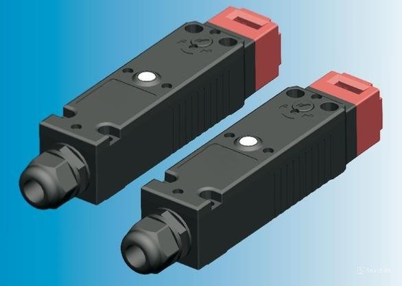
Electromagnetic type door lock switch MWQSD Series
- Standard with 4 sets of gold-plated contacts.
- Powerful locking force 1300N
- 12 contact types to choose from.
- Indicator light + emergency unlock function.
- 6 types of operation keys.
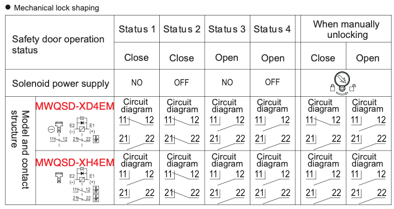
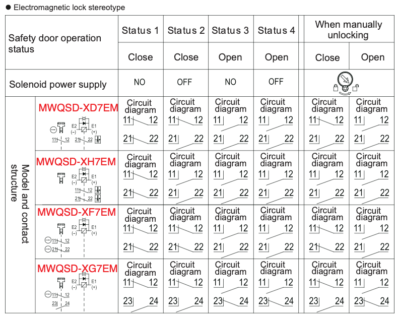
Electromagnetic type two sets of contact model composition
Switching contact type (door monitoring contact + locking monitoring contact)
- XD:1NC (jogging contact) + 1NC (jogging contact)
- XH: None + 2NC (slow-acting contact)
- XF:2NC(jogging contact)+ None
- XG:1NC/1NO(jogging contact)+ None
Door lock/release method
- 4:Mechanical locking/DC24V electromagnetic release
Head material E: plastic
Outlet hole type M:M20
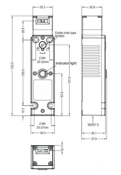
Dimensional drawing of electromagnetic safety door switch
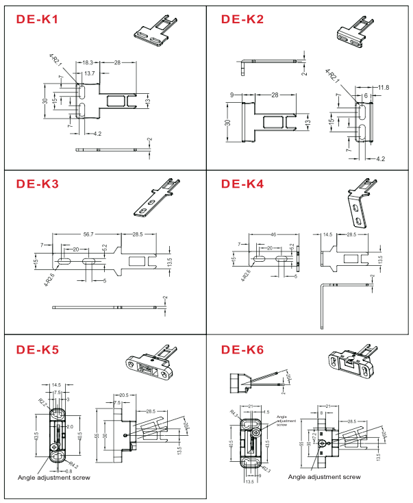
Product key size drawing and model
Product parameters
| Model | MWQSD Series | |
|---|---|---|
| Housing material | Pa66 Flame retardant | |
| Contact material | Silver alloy gold plating | |
| Protection level | IP67 (EN60947-5-01, except key-operated holes) | |
| Service life | More than 1 million times mechanical, more than 150,000 times electrical | |
| Tensile strength at locking | 1300N | |
| Rated insulation voltage | 300V | |
| Rated impulse withstand voltage | 2.5KV | |
| Rated open thermal current | 10A | |
| Use Category | AC-15 | DC-13 |
| Rated working voltage | 240V | 30V |
| Rated operating current | 3A | 2.3A |
| Rated limited short-circuit current | 1000A | |
| Forced disengagement Action force | ≥60N | |
| Forced Disengagement Distance | ≥10mm | |
| Allowable operating rate | 0.05~0.5m/s | |
| Allowable operating frequency | Max. 20 operations/min | |
| Ambient temperature | -20 ~ 60℃, no freezing | |
| Ambient Humidity | Below 83%RH | |
Indicator light
| Rated voltage | 24VDC | |
| Rated current | 1mA | |
| Light source color | Green | |
Solenoid
| Rated working voltage | DC24±10% | |
| Rated current | 200mA initial value | |
| Power | 4.8W | |
| Light source color | Class B(130) | |
Switches and Models
| Head Material | Solenoid voltage Indicator light | Lock/release method | Contact type (Door monitoring + locking monitoring) | Catheter port size |
|---|---|---|---|---|
| Resin | Solenoid: DC24 Green | Mechanical locking electromagnetic release | 1NC + 1NC | M20 |
| None + 2NC | M20 | |||
| Electromagnetic locking mechanical release | 1NC + 1NC | M20 | ||
| None + 2NC | M20 | |||
| 2NC + None | M20 | |||
| 1NC/1NO + None | M20 |
Action circuit and action characteristics
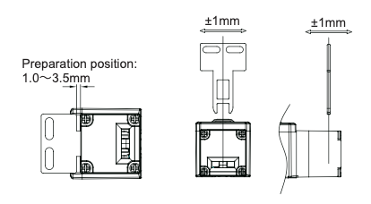
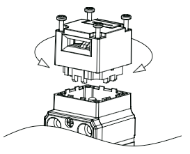
Installation
Loosen the 4 screws at the top of the head and rotate the head direction to select the appropriate operating key hole position before installation.
When installed in flush doors, it needs to be larger than the minimum radius.
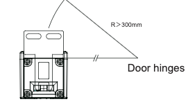
Please install the switch and operation key within the prepared position range (1 to 3.5 mm).
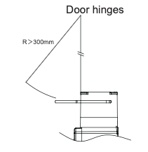
The permissible error in the installation of the operating key is within ±1mm from the center of the operating key insertion hole.