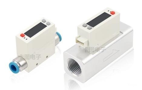
Gas Flow Sensor FM350
Principle characteristics
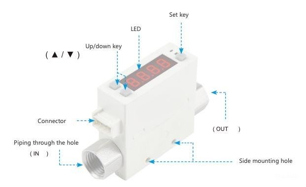
Thermal principle, gas mass flowmeter, display direction can be reversed 180°, easy to set and view 4-digit LED display.
Technical specification
- Display accuracy ± 3% F.S.
- Repeatability ± 3% F.S.
- Electronic display of instantaneous flow rate
- View accumulated traffic
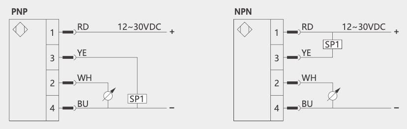
- With switch output NPN/PNP output function
- Analog: Voltage output 1~5 V
- Analog output: Current output 4~20 mA
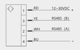
Wiring diagram
One switch + one analog
RS485 communication
Technical parameter
| Model number | 0005 | 0010 | 0050 | 0100 | 0200 | 1000 | 2000 |
|---|---|---|---|---|---|---|---|
| Dry air, nitrogen (N2), non-corrosive, non-flammable | |||||||
|
Sensing element Rated flow range Detection direction |
0 ~ 5 L/min | 0 ~ 10 L/min | 0 ~ 50 L/min | 0 ~ 100 L/min | 0 ~ 200 L/min | 0 ~ 1000 L/min | 0 ~ 2000 L/min |
| unidirectional | |||||||
|
display Instantanous flow |
0 ~ 5.25 L/min | 0 ~ 10.50 L/min | 0 ~ 52.5 L/min | 0 ~ 105.0 L/min | 0 ~ 210 L/min | 0 ~ 1050 L/min | 0 ~ 2100 L/min |
| 0.01 L/min | 0.01 L/min | 0.1 L/min | 0.1 L/min | 1 L/min | 1 L/min | 1 L/min | |
| linearity | |||||||
| ±3% F.S. + 1digit | |||||||
|
precision Analog output accuracy |
±3% F.S. + 1digit | ||||||
| ±3% F.S. + 1digit | |||||||
| ±3% F.S. | |||||||
|
switching output Reaction time |
800 ms (50 ms, 80 ms, 120 ms, 200 ms, 400 ms, 1500 ms Can be Selected) | ||||||
| Hysteresis mode, window mode, pulse mode(full scale 150 Hz) | |||||||
| tunable | |||||||
| YES | |||||||
|
Analog quantity exportation Voltage output |
Output voltage range: 1 ~ 5 V | ||||||
| Output Impedance: 1 KΩ | |||||||
| Output current range: 4 ~ 20 mA | |||||||
| Load Impedance: ≤ 300Ω | |||||||
|
Reaction time |
≤ 100 ms | ||||||
| RS485 JIS | |||||||
|
Power source Supply voltage |
12 ~ 24 V DC ± 10% | ||||||
| ≤ 50 mA | |||||||
| -0.09 ~ 0.8 MPa | |||||||
|
Pressure resistance |
1 MPa | ||||||
| IP40 | |||||||
|
Environment al requirement Medium temperature |
0 ~ 50 °C (no water dew and no ice) | ||||||
| Action: 0 ~ 50 °C, storage: - 10 ~ 60 °C (no water dew and no ice) | |||||||
| Operation and preservation: 35 ~ 85% R.H. (waterless dew) | |||||||
| ≥ 50 MΩ (500 V DC, between leads and plastic housing) | |||||||
| 1000 V AC 1 min (between leads and plastic housing) | |||||||
|
EMC |
IEC 61000-6-2, IEC 61000-6-4 | ||||||
|
Wire specification |
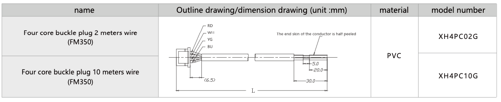
Ø4 Oil resistant PVC (0.25m 2) -4 cores | ||||||
|
Weight (including 2 m of wire) |
Approx. 109.3g (Ø6 connector); Approx. 112.7g (Ø8 connector); Approx. 118 g (Rc1⁄4 connector); Approx. 128.5g (Rc1⁄8 connector) | ||||||
※1: The standard inlet pressure is 300 kPa, outlet pressure is 1 atmosphere, and temperature condition is 25 °C (factory standard).
※2: -0.09 ~ 0.8MPa, 1 atmospheric pressure at the outlet, 25 °C temperature (factory standard)
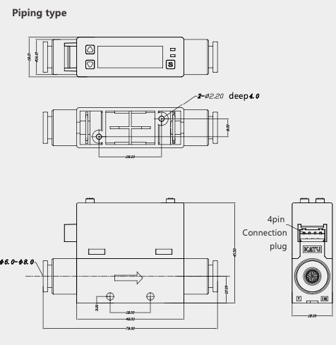
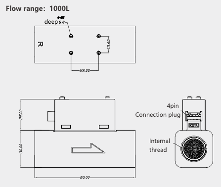
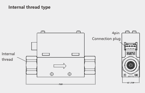
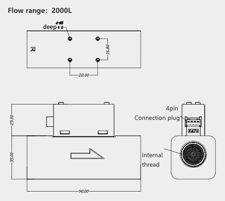
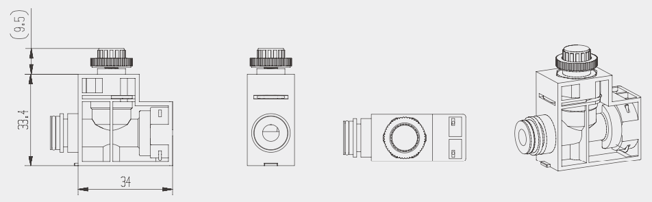
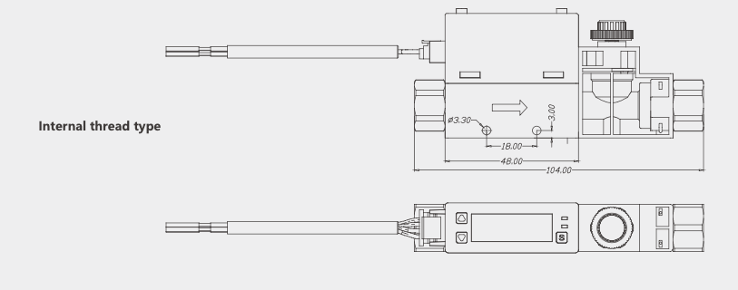
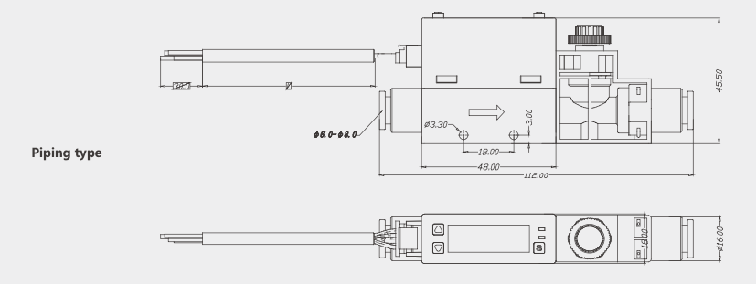
Size drawing (mm)
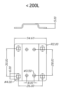
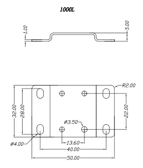
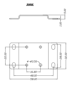
Mounting bracket
Regulating valve size diagram (mm)
Selection list
| FM350- / FM350- | 0005 | NV | D6 | - | - | expatiate |
|---|---|---|---|---|---|---|
| FM350- | FM350 Gas flow sensor | |||||
| 0005 | Flow range: 5 L/min | |||||
| 0010 | Flow range: 10 L/min | |||||
| 0050 | Flow range: 50 L/min | |||||
| 0100 | Flow range: 100 L/min | |||||
| 0200 | Flow range: 200 L/min | |||||
| 1000 | Flow range: 1000 L/min | |||||
| 2000 | Flow range: 2000 L/min | |||||
| NV | Output signal: NPN + analog 1 ~ 5V | |||||
| NA | Output signal: NPN + analog 4 ~ 20 mA | |||||
| PV | Output signal: PNP + analog 1 ~ 5V | |||||
| PA | Output signal: PNP + analog 4 ~ 20 mA | |||||
| R | Output signal: RS485 | |||||
| D6 | Nozzle diameter: Ø6mm quick connector, flow range ≤50L/min | |||||
| D8 | Nozzle diameter: Ø8mm quick connector, flow range 100/200L/min | |||||
| R18K | Nozzle diameter: Rc1/8 pipe tooth joint, flow range ≤50L/min | |||||
| G18K | Nozzle diameter: G1/8 internal thread, flow range ≤50L/min | |||||
| R14K | Nozzle diameter: Rc1/4 pipe tooth joint, flow range 100/200L/min | |||||
| G14K | Nozzle diameter: G1/4 internal thread, flow range 100/200L/min | |||||
| R12K | Nozzle diameter: Rc1/2 tooth joint, flow range 1000L/min | |||||
| G12K | Nozzle diameter: G1/2 internal thread, flow range 1000L/min | |||||
| R34K | Nozzle diameter: Rc3/4 pipe tooth joint, flow range 2000L/min | |||||
| G34K | Nozzle diameter: G3/4 internal thread, flow range 2000L/min | |||||
| - | No bracket | |||||
| -T | Tape carrier | |||||
| - | No regulating valve | |||||
| F | Tape regulating valve (Only ≤200L/min optional) |
Optional accessories - Electrical accessories
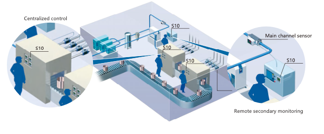
Application drawing

Technical parameter
- Input specification: Analog quantity (pulse) / PT100 is optional
- Display range: -199.9 ~ 999.9
- Temperature drift: ≤ ±0.015%FS /°C (typical value about ±75ppm/°C)
- Electromagnetic compatibility:
IEC61000-4-4 (electrical fast transient pulse group), ±4KV/5KHz;
IEC61000-4-5 (Surge), 4KV - Output function: Switch / analog quantity is optional
- Power supply: 24VDC ±20%
- Power consumption: ≤ 3W
- Operating environment: temperature -10~+60°C; Humidity ≤ 90%RH
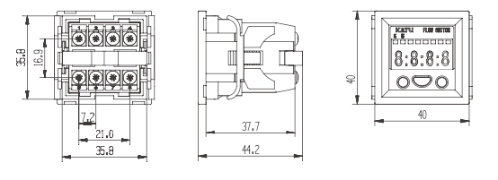
Size drawing (mm)
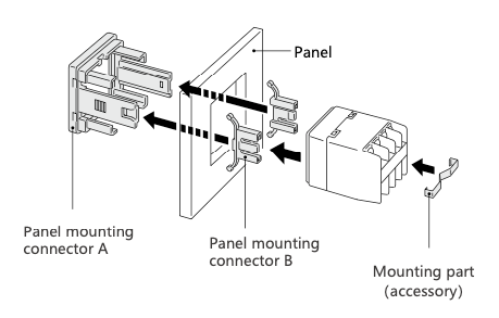
Panel mounting
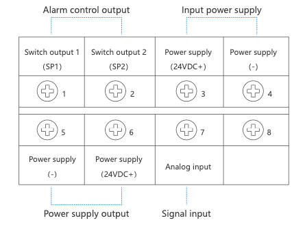
Wiring diagram
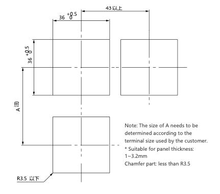
Panel opening size
| Order model | Technical Description | |
|---|---|---|
| S10-21 | Input signal: Analog quantity Output signal: Output by two switches |
Display unit: L/min |