Flow switch
Flow meter for water
Hygienic flow meter for milk and food Industry application
Flow meter for Diesel, LPG & Gases
Flow meter for compressed air
Non contract flow meter
Electromagnetic Flowmeter FM260
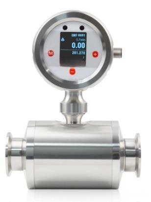
Product overview
According to Faraday's principle of electromagnetic induction, when a
conductor passes vertically through magnetic field B, it will induce a
voltage. U In the measurement of the flowmeter, the moving conductor is a
flowing conductive medium, the magnetic field B is emitted from the
direction perpendicular to the flowing medium, and the induced electro-
motive force U on the two electrodes E1 and E2 is directly proportional to
the flow rate V of the medium.
U=K×B×V×D
K- Meter constant
D- Internal probe spacing
After further processing, the induced electromotive force U is converted
into a standard electrical signal output or display
Functional characteristics
- Compact design saves installation space
- Anti-corrosion sensor technology
- All electronic design without viscosity of moving parts
- Automatic temperature compensation
- Pulse output/analog output /RS485 communication optional
- Low pressure loss
- Strong anti-fouling ability
Technical Specifications
- Measuring range: See range table
- Suitable pipe diameter: DN4... DN25 (see selection table)
- Measuring medium: conductive liquid (conductivity > 20uS/cm)
- Accuracy: ≤±0.5% range
- Repeatability: ≤±0.2% range
- Pressure resistance: 16 bar
- Supply voltage: 24±10%Vdc
- Current consumption: ≤80mA
- Electrical protection: reverse polarity protection, short circuit protection
- Output:
- Pulse output: NPN output, pull-up resistor $2\text{K}\Omega$
- Analog output: 4... 20mA, current limit 26mA, load resistance < 250Ω
- Response time: < 100ms
- Ambient temperature: -25... 85 °C
- Medium temperature: -40... 120 No thermal shock (optional high temperature 140°C)
- Materials:
- Electrode: stainless steel 316TI
- Process connection: stainless steel 316TI
- Measuring tube: PEEK
- Seal: EPDM
- Housing: stainless steel 304
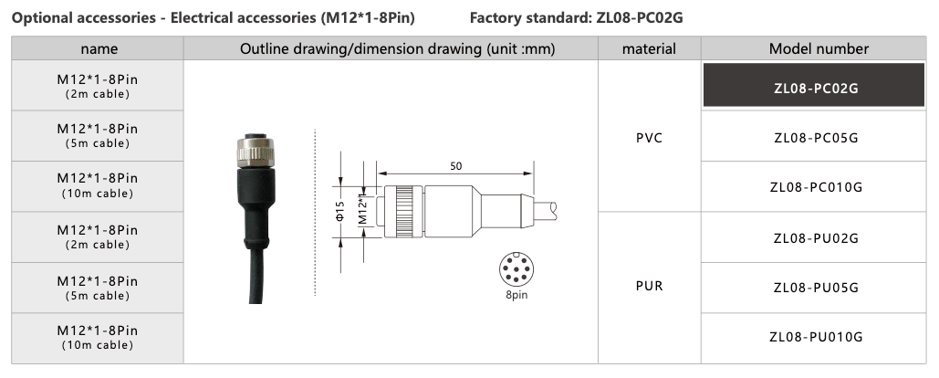
- Electrical connection: M12×1 connector
- Process connection: external thread/internal thread/sanitary chuck can be selected
Wiring diagram
8-core wire
| line | color | Feature |
|---|---|---|
| 2 | BN | power supply(+) |
| 7 | BU | power supply(-) |
| 8 | RD | RS485(A) |
| 4 | YE | RS485(B) |
| 6 | PK | pulse (+) |
| 1 | WH | pulse (-) |
| 3 | GN | electric current (-) |
| 5 | GY | electric current (+) |
5-core wire
| line | color | Feature |
|---|---|---|
| 1 | BN | power supply(+) |
| 3 | BU | power supply(-) |
| 5 | GY | Analog signal (mA) |
| 2 | WH | RS485 (A) |
| 4 | BK | RS485 (B) |
4-core wire
| line | color | Feature |
|---|---|---|
| 1 | BN | power supply(+) |
| 3 | BU | power supply(-) |
| 2 | WH | RS485(A) |
| 4 | BK | RS485(B) |
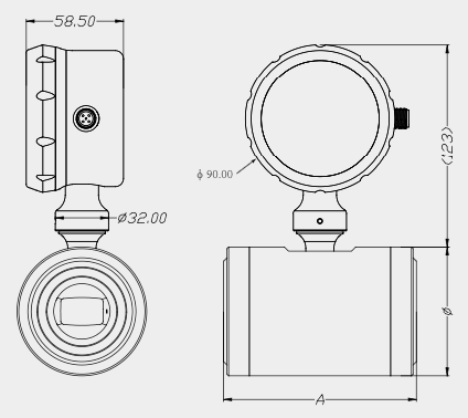
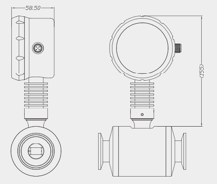
Dimension drawing(mm)
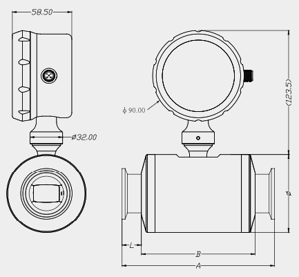
Chuck connection
| Specification and model | Chuck connection | Pipe diameter (DN) | A | B | $\phi$ | Measuring range (L/min) |
|---|---|---|---|---|---|---|
| FM260-H04 | 25.4 Sanitary chuck | 4 | 90 | 60 | 45 | 0.1-10 |
| FM260-H08 | 25.4 Sanitary chuck | 8 | 104 | 74 | 60 | 0.5-25 |
| FM260-H12 | 50.5 Sanitary chuck | 15 | 120 | 90 | 70 | 1-60 |
| FM260-H15 | 50.5 Sanitary chuck | 15 | 120 | 90 | 70 | 3-100 |
| FM260-H25 | 50.5 Sanitary chuck | 25 | 150 | 112 | 78 | 4-200 |
| FM260-H32 | 50.5 Sanitary chuck | 32 | 210 | 150 | 115 | 20-300 |
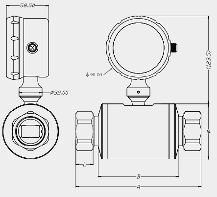
Internal thread connection
| Specification and model | Internal thread connection | Pipe diameter (DN) | A | B | $\phi$ | Effective screw (L) | Measuring range (L/min) |
|---|---|---|---|---|---|---|---|
| FM260-GK04 | G1/4" | 4 | 90 | 60 | 45 | 13 | 0.1-10 |
| FM260-GK08 | G1/2" | 8 | 122 | 74 | 60 | 13 | 0.5-25 |
| FM260-GK12 | G3/4" | 15 | 142 | 90 | 70 | 15 | 1-60 |
| FM260-GK15 | G3/4" | 15 | 142 | 90 | 70 | 15 | 3-100 |
| FM260-GK25 | G1-1/4" | 25 | 174 | 112 | 78 | 20 | 4-200 |
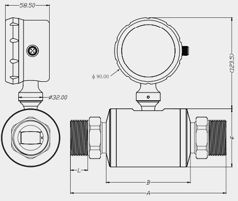
External thread connection
| Specification and model | External thread connection | Pipe diameter (DN) | A | B | $\phi$ | Effective screw (L) | Measuring range (L/min) |
|---|---|---|---|---|---|---|---|
| FM260-GM04 | G1/4" | 4 | 110 | 60 | 45 | 12 | 0.1-10 |
| FM260-GM08 | G1/2" | 8 | 141 | 74 | 60 | 18 | 0.5-25 |
| FM260-GM12 | G1" | 15 | 170 | 90 | 70 | 20 | 1-60 |
| FM260-GM15 | G1" | 15 | 170 | 90 | 70 | 20 | 3-100 |
| FM260-GM25 | G1-1/2" | 25 | 207 | 112 | 78 | 25 | 4-200 |
Tie rod flange connection
| Specification and model | pull rod flange | Pipe diameter (DN) | A | $\phi$ | Measuring range (L/min) |
|---|---|---|---|---|---|
| FM260-F04 | DN15 | 4 | 63 | 45 | 0.1-10 |
| FM260-F08 | DN25 | 8 | 80 | 60 | 0.5-25 |
| FM260-F12 | DN32 | 15 | 92 | 70 | 1-60 |
| FM260-F15 | DN32 | 15 | 92 | 70 | 3-100 |
| FM260-F25 | DN32 | 25 | 116 | 78 | 4-200 |
High temperature type(>120°)
Selection list
| FM260 Electromagnetic Flowmeter Model Code | ||||||
|---|---|---|---|---|---|---|
| Position 1 | Position 2 | Position 3 | Position 4 | Position 5 | Position 6 | Instructions (Description) |
| FM 260 - | FM 260 Electromagnetic flowmeter | |||||
| H | Process connection: Chuck connection | |||||
| G K | Process connection: G thread internal teeth | |||||
| G M | Process connection: G thread external teeth | |||||
| F | Process connection: Pull rod flange | |||||
| 04 | Caliber: DN 4 | |||||
| 08 | Caliber: DN 8 | |||||
| 15 | Caliber: DN 15 | |||||
| 25 | Caliber: DN 25 | |||||
| P R | Pulse/Current /RS485 (8 cores) | |||||
| R A | RS485/analog mA (5 cores) | |||||
| R S | RS485 communication (4 cores) | |||||
| - | Medium temperature: -20... 120 °C | |||||
| H 1 | Medium temperature: -20... 140 °C | |||||
| H 2 | Medium temperature: -40... 120 °C | |||||
| H 3 | Medium temperature: -40... 140 °C | |||||
| - | Sealing material: Silicone (-40...120 °C coolant) | |||||
| K | Sealing material: Perfluoroether | |||||
| E | Sealing material: EPDM | |||||
| F | Sealing material: Fluorine rubber (0...120 °C) | |||||
| N | Sealing material: Nitrile rubber | |||||